VD = 2 × I × R × L / 1000
Example: Enter current, voltage, distance, material, wire size, and target drop
Quick answer: Use this voltage drop calculator workflow to choose phase, source voltage, load current, one-way distance, conductor material, wire size, and a project design target before comparing results. Single-phase uses VD = 2×I×R×L/1000 or 2×K×I×L/CM; three-phase replaces the loop multiplier with √3. NEC informational notes are commonly used as design targets, not standalone final answers. Use the Voltage Drop Calculator and Wire Size Calculator for the actual run.
Voltage drop is one of the most critical considerations in electrical system design and troubleshooting. Understanding how to calculate and control voltage drop ensures that electrical equipment receives adequate voltage for proper operation while maintaining safety and efficiency standards.
This guide focuses on practical voltage drop calculations for single-phase, three-phase, and DC circuits. It shows how to compute volts of drop, percent voltage drop, and conductor sizes, and how to compare results with common NEC informational-note design targets (about 3% branch circuits and about 5% feeders plus branch circuits combined).
If you primarily need numeric results, you can start with the Voltage Drop Calculator and Wire Size Calculator, then return here for derivations, assumptions, and engineering detail.
Concept: What is Voltage Drop?
Voltage drop is the reduction in voltage that occurs when current flows through the resistance of electrical conductors. As electricity travels from the source to the load, some voltage is "lost" due to the inherent resistance of the wires, connections, and other circuit components.
The Physics Behind Voltage Drop
When current flows through a conductor, the conductor's resistance causes a voltage drop according to Ohm's Law:
Voltage Drop = Current × Resistance VD = I × R
This voltage drop represents energy that is converted to heat in the conductor, reducing the voltage available at the load.
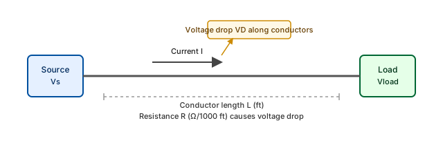
Figure 1 – Single-phase branch circuit showing source voltage Vs, conductor length L with resistance R, and reduced load voltage Vload due to voltage drop VD along the conductors.
Why Voltage Drop Matters
Excessive voltage drop can cause:
- Equipment malfunction: Motors may not start or may overheat
- Reduced efficiency: Lights may be dim, heaters may not reach full capacity
- Shortened equipment life: Low voltage can damage sensitive electronics
- Safety hazards: Overheating conductors and equipment failures
- Code and specification issues: NEC informational notes and many project specifications include voltage drop design limits that may be treated as enforceable criteria by authorities having jurisdiction
Standards: NEC Voltage Drop Guidance
The National Electrical Code (NEC) does not set hard prescriptive limits for branch-circuit or feeder voltage drop in the main code text, but informational notes in key articles provide widely used design targets to help ensure proper equipment operation.
NEC Informational-Note Design Targets
Article 210.19(A)(1) – Branch Circuits (Informational Note):
- Aim for about 3% voltage drop on individual branch circuits
- Aim for about 5% total voltage drop for feeders plus branch circuits
Article 215.2(A)(1) – Feeders (Informational Note):
- Aim for about 3% voltage drop on feeders
- Aim for about 5% total voltage drop for feeders plus branch circuits
Practical Voltage Drop Limits
| Circuit Type | Typical Design Target | Approximate Upper Range* |
|---|---|---|
| Branch Circuits | 3% | 5% |
| Feeders | 3% | 5% |
| Total System | 5% | 8% |
| Motor Circuits (running) | 3–5% | 8–10% |
*Values in this table reflect common U.S. design practice informed by NEC informational notes, IEEE-style system design guidance, and typical utility criteria. Project-specific limits must follow the current NEC edition, local amendments, utility requirements, and equipment manufacturer data.
Calculation: Voltage Drop Methods
Method 1: Basic Ohm's Law Calculation
For simple DC circuits or single-phase AC circuits with predominantly resistive loads using conductor resistance in ohms per 1000 feet:
VD = 2 × I × R × L / 1000
Where:
- VD = Voltage drop (volts)
- I = Current (amperes)
- R = Conductor resistance (ohms per 1000 feet)
- L = One-way length (feet)
- 2 = Factor for round-trip current path (out and back)
Method 2: Conductor Resistance Formula
For single-phase, two-conductor (out-and-back) circuits using resistivity constants in ohm‑circular‑mil per foot:
VD = (2 × K × I × L) / CM
Where:
- K = Resistivity constant (12.9 for copper, 21.2 for aluminum)
- I = Current (amperes)
- L = One-way length (feet)
- CM = Circular mil area of conductor
For balanced three-phase circuits, analogous formulas use √3 in place of 2 together with the appropriate conductor geometry; many design references instead tabulate R and X directly in Ω/1000 ft as in Method 3.
Method 3: Three-Phase Systems
For balanced three-phase systems using resistance in ohms per 1000 feet:
VD = √3 × I × R × L / 1000
Where:
- √3 = 1.732 (three-phase factor)
- R = Conductor resistance (ohms per 1000 feet)
- L, I as defined above
Method 4: AC Systems with Reactance
For AC circuits considering both resistance and reactance using impedance data in ohms per 1000 feet:
- Single-phase (two-conductor): VD = 2 × I × L × √(R² + X²) / 1000
- Three-phase (balanced): VD = √3 × I × L × √(R² + X²) / 1000
Where:
- R = Resistance per conductor (ohms per 1000 feet)
- X = Reactance per conductor (ohms per 1000 feet)
- I = Load current (amperes)
- L = One-way length from source to load (feet)
Percent Voltage Drop
Once VD is known, percent voltage drop is:
VD% = 100 × VD / V_source
Where V_source is the nominal/source voltage of the circuit.
Summary of Common Voltage Drop Formulas (R, X in Ω/1000 ft)
| System Type | Formula (voltage drop VD, in volts) | Notes |
|---|---|---|
| DC / single-phase (resistive) | VD = 2 × I × R × L / 1000 | Two-conductor loop, resistance only |
| Single-phase AC (with R, X) | VD = 2 × I × L × √(R² + X²) / 1000 | Two-conductor loop, uses impedance magnitude per 1000 ft |
| Three-phase (balanced, resistive) | VD = √3 × I × R × L / 1000 | Line-to-line systems, resistance only |
| Three-phase AC (with R, X) | VD = √3 × I × L × √(R² + X²) / 1000 | Balanced systems using impedance magnitude per 1000 ft |
| Percent drop | VD% = 100 × VD / V_source | Compare with project/NEC-design targets |
Calculation Workflow: Step-by-Step
Calculator Workflow: Single-Phase Branch Circuit
Use this workflow for a long single-phase branch circuit before choosing a conductor:
- Enter the actual voltage, current, one-way distance, conductor material, and candidate AWG in the Voltage Drop Calculator.
- Compare the calculated percent drop with the project target or NEC informational-note design target being used on the job.
- If the drop is too high, test the next larger conductor sizes until the calculator result is inside the design target.
- Send the candidate conductor to the Wire Size Calculator to verify ampacity, insulation, terminal temperature, and adjustment factors.
- Document both checks together: voltage-drop sizing is not a substitute for ampacity, overcurrent protection, or equipment terminal requirements.
Calculator Workflow: Three-Phase Feeder
Use the same calculator-led approach for balanced three-phase feeders:
- Select the three-phase option and enter line-to-line voltage, line current, one-way feeder length, material, and candidate conductor size.
- Use the calculator output to compare volts of drop and percent drop against the design target adopted for the project.
- For longer feeders, larger kcmil conductors, low power-factor loads, or magnetic raceways, compare the simplified resistance result with a check based on NEC Chapter 9, Table 9 R and X values.
- Verify the selected conductor against ampacity, temperature, termination, raceway-fill, and overcurrent-protection requirements before treating the voltage-drop result as usable.
Design: Conductor Sizing for Voltage Drop
Sizing Process
- Calculate required conductor area:
- CM = (K × I × L) / VD_allowable
- Select next larger standard size:
- Choose conductor with CM area equal to or greater than calculated
- Verify ampacity:
- Ensure conductor can carry the load current safely
Conductor Properties Table
| AWG / kcmil | Copper CM | Aluminum CM | Cu R (Ω/1,000 ft) 75°C | Al R (Ω/1,000 ft) 75°C | Cu Ampacity (75°C) | Al Ampacity (75°C) |
|---|---|---|---|---|---|---|
| 14 AWG | 4,110 | — | 3.07 | — | 15 A | — |
| 12 AWG | 6,530 | — | 1.93 | — | 20 A | — |
| 10 AWG | 10,380 | 10,380 | 1.21 | 1.99 | 30 A | 25 A |
| 8 AWG | 16,510 | 16,510 | 0.764 | 1.26 | 50 A | 40 A |
| 6 AWG | 26,240 | 26,240 | 0.491 | 0.808 | 65 A | 50 A |
| 4 AWG | 41,740 | 41,740 | 0.308 | 0.508 | 85 A | 65 A |
| 3 AWG | 52,620 | 52,620 | 0.245 | 0.403 | 100 A | 75 A |
| 2 AWG | 66,360 | 66,360 | 0.194 | 0.319 | 115 A | 90 A |
| 1 AWG | 83,690 | 83,690 | 0.154 | 0.253 | 130 A | 100 A |
| 1/0 AWG | 105,600 | 105,600 | 0.122 | 0.201 | 150 A | 120 A |
| 2/0 AWG | 133,100 | 133,100 | 0.0967 | 0.159 | 175 A | 135 A |
| 3/0 AWG | 167,800 | 167,800 | 0.0766 | 0.126 | 200 A | 155 A |
| 4/0 AWG | 211,600 | 211,600 | 0.0608 | 0.100 | 230 A | 180 A |
| 250 kcmil | 250,000 | 250,000 | 0.0515 | 0.0847 | 255 A | 205 A |
| 350 kcmil | 350,000 | 350,000 | 0.0367 | 0.0603 | 310 A | 240 A |
| 500 kcmil | 500,000 | 500,000 | 0.0258 | 0.0424 | 380 A | 310 A |
Resistance values: AC resistance at 75°C in steel conduit per NEC Chapter 9, Table 9 reference basis. Ampacity: in conduit (not more than 3 current-carrying conductors), 75°C column, from NEC Table 310.16. Bold rows added for completeness covering common service and feeder sizes. Aluminum minimum size is 8 AWG per general practice; 14–12 AWG aluminum is not commonly used for branch circuits. Reactance X (from NEC Chapter 9 Table 9): ranges from ~0.073 Ω/1,000 ft (14 AWG in steel conduit) to ~0.033 Ω/1,000 ft (500 kcmil); at 60 Hz and typical power frequencies X is secondary to R for conductors up to ~4/0 AWG but becomes significant in large kcmil feeders. Always confirm against the NEC edition adopted by the AHJ and applicable amendments.
Minimum Conductor Size for Common 120V Single-Phase Loads (3% VD Target)
| Load (A) | 25 ft | 50 ft | 75 ft | 100 ft | 150 ft | 200 ft |
|---|---|---|---|---|---|---|
| 15 A | 14 AWG | 14 AWG | 12 AWG | 10 AWG | 8 AWG | 6 AWG |
| 20 A | 14 AWG | 12 AWG | 10 AWG | 8 AWG | 6 AWG | 4 AWG |
| 30 A | 12 AWG | 10 AWG | 8 AWG | 8 AWG | 6 AWG | 4 AWG |
| 40 A | 10 AWG | 8 AWG | 6 AWG | 6 AWG | 4 AWG | 2 AWG |
| 50 A | 10 AWG | 8 AWG | 6 AWG | 4 AWG | 2 AWG | 1/0 AWG |
Based on VD = 2×K×I×L/CM, K=12.9 copper, 120V source, 3% target (VD_max = 3.6 V). Conductor selected is the smallest standard size meeting the voltage drop criterion; always verify ampacity per NEC 310.16 and apply derating for conduit fill, temperature, or continuous loads as applicable.
Minimum Conductor Size for Common 240V Single-Phase Loads (3% VD Target)
EV chargers, HVAC condensers, electric ranges, dryers, and sub-panels. VD_max = 240 × 0.03 = 7.2 V.
| Load (A) | Typical Application | 25 ft | 50 ft | 75 ft | 100 ft | 150 ft | 200 ft |
|---|---|---|---|---|---|---|---|
| 15 A | Small A/C, baseboard heat | 14 AWG | 14 AWG | 12 AWG | 12 AWG | 10 AWG | 8 AWG |
| 20 A | 240V outlets, well pump | 14 AWG† | 12 AWG | 12 AWG | 10 AWG | 8 AWG | 6 AWG |
| 30 A | Dryer, water heater | 10 AWG† | 10 AWG† | 10 AWG | 8 AWG | 6 AWG | 4 AWG |
| 40 A | Range, large A/C, EV Level 2 | 8 AWG† | 8 AWG† | 8 AWG† | 8 AWG | 6 AWG | 4 AWG |
| 48 A | EV Level 2 EVSE (48A OCPD) | 6 AWG† | 6 AWG† | 6 AWG† | 6 AWG | 4 AWG | 2 AWG |
| 60 A | Large sub-panel, EV fast | 6 AWG† | 6 AWG† | 6 AWG† | 4 AWG | 2 AWG | 1/0 AWG |
| 80 A | Sub-panel/service feeder | 4 AWG† | 4 AWG† | 4 AWG† | 2 AWG | 1/0 AWG | 2/0 AWG |
| 100 A | 100A service feeder | 2 AWG† | 2 AWG† | 2 AWG† | 2 AWG | 1/0 AWG | 3/0 AWG |
† Ampacity (not voltage drop) controls minimum size for these short runs per NEC Table 310.16, 75°C column. Verify continuous load factor (125% per NEC 210.20/215.3) and apply derating as needed.
Note on EV chargers (NEC 625 / NEC 220.57 reference context): EVSE loads are typically treated as continuous (3+ hours). An EVSE rated 40A requires minimum 50A circuit (40 × 1.25); a 48A EVSE requires 60A circuit. Conductor must meet both ampacity (for the OCPD size) and voltage drop criteria. Verify the adopted NEC Section 625 language, equipment instructions, and AHJ requirements before finalizing EVSE conductors.
Minimum Conductor Size for Common 480V Three-Phase Loads (3% VD Target)
| Load (A) | 50 ft | 100 ft | 150 ft | 200 ft | 300 ft | 500 ft |
|---|---|---|---|---|---|---|
| 30 A | 12 AWG | 12 AWG | 12 AWG | 10 AWG | 8 AWG | 6 AWG |
| 50 A | 12 AWG | 10 AWG | 8 AWG | 8 AWG | 6 AWG | 4 AWG |
| 100 A | 10 AWG | 8 AWG | 6 AWG | 4 AWG | 2 AWG | 1/0 AWG |
| 150 A | 8 AWG | 6 AWG | 4 AWG | 2 AWG | 1/0 AWG | 3/0 AWG |
| 200 A | 8 AWG | 4 AWG | 2 AWG | 1/0 AWG | 3/0 AWG | 350 kcmil |
Based on VD = √3×K×I×L/CM, K=12.9 copper, 480V source, 3% target (VD_max = 14.4 V). Always verify ampacity and apply derating as applicable.
Factors Affecting Voltage Drop
Conductor Material
- Copper: Lower resistance, better conductivity
- Aluminum: Higher resistance, requires larger size for same performance
Temperature Effects
- Higher temperatures: Increase conductor resistance
- Temperature coefficient: Copper ≈ 0.00393/°C, Aluminum ≈ 0.00403/°C
Frequency Effects (AC Systems)
- Skin effect: Current concentrates near conductor surface at high frequencies
- Proximity effect: Magnetic fields from adjacent conductors affect current distribution
- Power factor and harmonics: Reactive and non-linear loads change current and voltage relationships; see Power Factor Fundamentals and the Power Calculator for more detail
Installation Conditions
- Conduit fill: Multiple conductors increase temperature and resistance
- Ambient temperature: Higher ambient temperatures require derating
- Conductor spacing: Affects reactance in AC systems
Practical Applications
Motor Circuits
Motors are particularly sensitive to voltage drop:
- Starting current: Often 6–8 times running current (exact value is motor-dependent)
- Voltage sensitivity: A 10% voltage drop typically reduces available torque by roughly 19% (torque ∝ V² for many induction motors)
- Design practice: Many U.S. design guides limit running voltage drop on motor circuits to about 3% and starting drop to roughly 10–15%; always confirm limits with the applicable NEC edition, equipment data, and utility requirements
Lighting Circuits
Voltage drop affects lighting performance:
- Incandescent lamps: Light output varies with voltage squared
- Fluorescent lamps: May not start with excessive voltage drop
- LED lighting: Generally more tolerant but still affected
Long Distance Feeders
Special considerations for long runs:
- Economic analysis: Balance conductor cost vs. energy losses
- Voltage regulation: May require voltage regulators or transformers
- Power factor: Reactive loads increase voltage drop
- Design references: For more detailed mitigation options, see Voltage Drop Mitigation and the Wire Size Selection Guide
Troubleshooting Voltage Drop Problems
Symptoms of Excessive Voltage Drop
- Motors: Slow starting, overheating, reduced torque
- Lights: Dimming, flickering, premature failure
- Electronics: Malfunction, reset issues, shortened life
- Heating elements: Reduced heat output, longer heating times
Measurement Techniques
- No-load voltage: Measure voltage with no current flowing
- Full-load voltage: Measure voltage under normal operating conditions
- Voltage drop: Calculate difference between no-load and full-load
- Documented procedures: For test methods and instrumentation basics, see Electrical Testing Fundamentals
Common Causes
- Undersized conductors: Most common cause
- Poor connections: Loose or corroded connections
- Damaged conductors: Nicked or partially severed wires
- Overloaded circuits: Current exceeding design values
Solutions
- Increase conductor size: Most effective solution
- Reduce circuit length: Relocate panels or loads
- Improve connections: Clean and tighten all connections
- Load redistribution: Balance loads across multiple circuits
Advanced Design and Economic Considerations
Voltage Drop in Parallel Conductors
When using parallel conductors:
- Equal sharing: Ensure conductors have equal impedance
- Installation requirements: Follow NEC Article 310.10(H)
- Calculation method: Divide total current by number of parallel paths
Harmonic Effects
Non-linear loads create harmonics that affect voltage drop:
- Increased RMS current: Harmonics increase effective current
- Neutral conductor: May carry significant current in three-phase systems
- K-factor: Derating factor for transformers with harmonic loads
- Further reading: See Power Quality Analysis for broader harmonic and distortion impacts
Economic Analysis
Consider total cost of ownership:
- Initial cost: Larger conductors cost more upfront
- Energy losses: I²R losses continue throughout system life
- Equipment life: Proper voltage extends equipment life
- Maintenance costs: Reduced with proper voltage levels
Standards and Best Practices
NEC Requirements Summary
- Branch circuits: About 3% voltage drop is a widely used design target from NEC informational notes
- Feeders: About 3% voltage drop is a common design target from NEC informational notes
- Total system: About 5% total voltage drop (feeders plus branch circuits) is a common overall design target
- Motor circuits: Many IEEE- and utility-style guides limit running voltage drop to about 3%; starting-drop limits (often on the order of 10–15%) are set by project specifications and equipment manufacturers
Design Best Practices
- Conservative approach: Design for 2% or less when practical
- Future expansion: Consider potential load growth
- Load analysis: Use realistic load factors, not nameplate ratings
- Documentation: Maintain voltage drop calculations for inspections
Inspection Considerations
- Plan review: Voltage drop calculations may be required
- Field verification: Inspectors may request voltage measurements
- Code updates: Stay current with NEC revisions
Calculation Tools and Resources
Manual Calculation Methods
- Ohm's Law: Basic calculations for simple circuits
- NEC Chapter 9: Tables for conductor properties
- Manufacturer data: Specific conductor characteristics
EleCalculator Tools
- Voltage Drop Calculator – single-phase and three-phase voltage drop, percent drop, and NEC-style analysis
- Wire Size Calculator – integrates ampacity, derating, and voltage drop for conductor selection
- Motor Cable Size Calculator – motor branch/feeder sizing with distance and voltage-drop considerations
- Power Calculator – power, current, and power-factor relationships for loss and loading analysis
Software Tools
- Electrical design software: AutoCAD Electrical, ETAP, SKM
- Online calculators: Web-based voltage drop calculators
- Mobile apps: Smartphone apps for field calculations
Reference Standards
- NEC Article 210: Branch circuit requirements
- NEC Article 215: Feeder requirements
- NEC Chapter 9: Tables and calculation methods
- IEEE Standards: Additional guidance for specific applications
Code adoption note: NFPA 70 is adopted and amended by jurisdiction. Always confirm the edition and amendments in force with the authority having jurisdiction (AHJ) before finalizing design criteria.
Summary
Voltage drop calculations are essential for proper electrical system design and operation. Key points to remember:
- NEC informational-note design targets: about 3% for branch circuits and feeders, about 5% total system
- Calculation methods: Various formulas for different system types
- Conductor sizing: Balance voltage drop, ampacity, and cost
- Troubleshooting: Identify and correct voltage drop problems
- Best practices: Conservative design for reliable operation
Proper voltage drop analysis ensures equipment operates efficiently, safely, and reliably while meeting code requirements and minimizing energy losses.
Next Steps
Continue your electrical engineering education with these related topics:
- Wire Size Selection Guide: Comprehensive conductor sizing methods including ampacity and voltage drop
- Series and Parallel Circuits: Circuit configurations that influence voltage distribution and drop
- Power Factor Fundamentals: How reactive loads and power factor affect current and voltage drop
- Motor Control Circuits: Applying voltage drop principles in motor control and starting circuits
- Voltage Drop Mitigation: System-level strategies when basic conductor upsizing is not sufficient
Understanding voltage drop is crucial for designing electrical systems that operate reliably and efficiently throughout their service life.